Pada bahasan sebelumnya, kita telah membangun VLAN dengan
skema berikut :

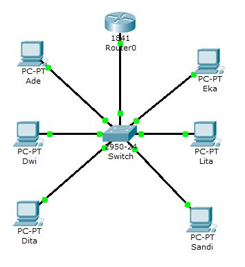
Namun, semua PC belum dapat saling terkoneksi. Oleh karena
itu, dibutuhkan sebuah router sebagai penghubung antar VLAN. Buat skema VLAN
yang kedua seperti berikut :
Dan untuk alokasi IP Address- nya sebagai berikut :
|
Nama
PC
|
IP Address
|
Subnet Mask
|
Gateway
|
|
Ade
|
192.168.1.1
|
255.255.255.0
|
192.168.1.10
|
|
Dwi
|
192.168.1.2
|
255.255.255.0
|
|
|
Dita
|
192.168.1.3
|
255.255.255.0
|
|
|
Eka
|
192.168.2.1
|
255.255.255.0
|
192.168.2.10
|
|
Lita
|
192.168.2.2
|
255.255.255.0
|
|
|
Sandi
|
192.168.2.3
|
255.255.255.0
|
Lalu pastikan port Fa0/0 pada router dalam keadaan ON. Untuk
mengaktifkannya, klik Router0 pilih tab Config > FastEthernet0/0

Router dihubungkan ke Switch dengan menggunakan port Fa0/7.
Sehingga port Fa0/7 pada Switch perlu diubah menjadi mode “Trunk”. Untuk
konfigurasinya, klik Switch lalu pilih tab CLI dan ketikan perintah berikut.
Switch>en
Switch#conf
term
Enter
configuration commands, one per line.
End with CNTL/Z.
Switch(config)#int
fa0/7
Switch(config-if)#switchp
mod ac
Switch(config-if)#switchp
mod trunk
Kemudian beralih ke Router0. Klik Router0 dan pilih tab CLI
lalu ketikan perintah berikut :
Router>en
Router#conf
term
Enter
configuration commands, one per line.
End with CNTL/Z.
Router(config)#int
fa0/0.2
%LINK-5-CHANGED:
Interface FastEthernet0/0.2, changed state to up
%LINEPROTO-5-UPDOWN:
Line protocol on Interface FastEthernet0/0.2, changed state to up
Router(config-subif)#encapsulation
dot1q 2
Router(config-subif)#ip
address 192.168.1.10 255.255.255.0
Router(config-subif)#ex
Router(config)#int
fa0/0.3
%LINK-5-CHANGED:
Interface FastEthernet0/0.3, changed state to up
%LINEPROTO-5-UPDOWN:
Line protocol on Interface FastEthernet0/0.3, changed state to up
Router(config-subif)#encapsulation
dot1q 3
Router(config-subif)#ip
address 192.168.2.10 255.255.255.0
Router(config-subif)#ex
Router(config)#ex
Router#
%SYS-5-CONFIG_I:
Configured from console by console
Router#show
ip route
Codes: C -
connected, S - static, I - IGRP, R - RIP, M - mobile, B - BGP
D - EIGRP, EX - EIGRP external, O -
OSPF, IA - OSPF inter area
N1 - OSPF NSSA external type 1, N2 -
OSPF NSSA external type 2
E1 - OSPF external type 1, E2 - OSPF
external type 2, E - EGP
i - IS-IS, L1 - IS-IS level-1, L2 -
IS-IS level-2, ia - IS-IS inter area
* - candidate default, U - per-user
static route, o - ODR
P - periodic downloaded static route
Gateway of
last resort is not set
C 192.168.1.0/24 is directly connected,
FastEthernet0/0.2
C 192.168.2.0/24 is directly connected,
FastEthernet0/0.3
Keterangan :
- Untuk IP Address di Router0 menggunakan IP Address alias.
- Perintah int fa0/0.2 merupakan perintah untuk membuat IP Address alias yang berhubungan dengan vlan 2 (TKJ). Perhatikan angka 2 setelah tanda titik!
- Perintah int fa0/0.3 merupakan perintah untuk membuat IP Address alias yang berhubungan dengan vlan 3 (TEI). Perhatikan angka 3 setelah tanda titik!
- Perintah encapsulation dot1q 2 merupakan perintah agar IP Address alias yang akan dibuat mampu berhubungan dengan vlan 2 (TKJ). Perhatikan angka 2 setelah encapsulation dot1q!
- Perintah encapsulation dot1q 3 merupakan perintah agar IP Address alias yang akan dibuat mampu berhubungan dengan vlan 3 (TEI). Perhatikan angka 3 setelah encapsulation dot1q!
- Perintah ip address 192.168.1.10 255.255.255.0 merupakan perintah untuk mengeset IP Address.
· Masih di tab CLI, cek koneksi Router0 dengan seluruh PC
menggunakan perintah ping seperti berikut ini :
Router#ping
192.168.1.1
Type escape
sequence to abort.
Sending 5,
100-byte ICMP Echos to 192.168.1.1, timeout is 2 seconds:
.!!!!
Success rate
is 80 percent (4/5), round-trip min/avg/max = 31/50/62 ms
Router#ping
192.168.1.2
Type escape
sequence to abort.
Sending 5,
100-byte ICMP Echos to 192.168.1.2, timeout is 2 seconds:
.!!!!
Success rate
is 80 percent (4/5), round-trip min/avg/max = 47/58/63 ms
Router#ping
192.168.1.3
Type escape
sequence to abort.
Sending 5,
100-byte ICMP Echos to 192.168.1.3, timeout is 2 seconds:
.!!!!
Success rate
is 80 percent (4/5), round-trip min/avg/max = 31/54/63 ms
Router#ping
192.168.2.1
Type escape
sequence to abort.
Sending 5,
100-byte ICMP Echos to 192.168.2.1, timeout is 2 seconds:
.!!!!
Success rate
is 80 percent (4/5), round-trip min/avg/max = 48/58/63 ms
Router#ping
192.168.2.2
Type escape
sequence to abort.
Sending 5,
100-byte ICMP Echos to 192.168.2.2, timeout is 2 seconds:
.!!!!
Success rate
is 80 percent (4/5), round-trip min/avg/max = 62/62/63 ms
Router#ping
192.168.2.3
Type escape
sequence to abort.
Sending 5,
100-byte ICMP Echos to 192.168.2.3, timeout is 2 seconds:
.!!!!
Success rate
is 80 percent (4/5), round-trip min/avg/max = 46/58/63 ms
Hasilnya, koneksi antara Router0 dengan seluruh PC berjalan
dengan baik.
Selanjutnya tes koneksi PC dengan PC lainnya. Sehingga
hasilnya akan seperti berikut :
PC>ping
192.168.1.1
Pinging
192.168.1.1 with 32 bytes of data:
Reply from
192.168.1.1: bytes=32 time=110ms TTL=127
Reply from
192.168.1.1: bytes=32 time=124ms TTL=127
Reply from
192.168.1.1: bytes=32 time=110ms TTL=127
Reply from
192.168.1.1: bytes=32 time=124ms TTL=127
Ping
statistics for 192.168.1.1:
Packets: Sent = 4, Received = 4, Lost = 0
(0% loss),
Approximate
round trip times in milli-seconds:
Minimum = 110ms, Maximum = 124ms, Average =
117ms
PC>ping
192.168.1.2
Pinging
192.168.1.2 with 32 bytes of data:
Reply from
192.168.1.2: bytes=32 time=109ms TTL=127
Reply from
192.168.1.2: bytes=32 time=93ms TTL=127
Reply from
192.168.1.2: bytes=32 time=124ms TTL=127
Reply from
192.168.1.2: bytes=32 time=125ms TTL=127
Ping
statistics for 192.168.1.2:
Packets: Sent = 4, Received = 4, Lost = 0 (0%
loss),
Approximate
round trip times in milli-seconds:
Minimum = 93ms, Maximum = 125ms, Average =
112ms
PC>ping
192.168.1.3
Pinging
192.168.1.3 with 32 bytes of data:
Reply from
192.168.1.3: bytes=32 time=78ms TTL=127
Reply from
192.168.1.3: bytes=32 time=125ms TTL=127
Reply from
192.168.1.3: bytes=32 time=125ms TTL=127
Reply from
192.168.1.3: bytes=32 time=109ms TTL=127
Ping
statistics for 192.168.1.3:
Packets: Sent = 4, Received = 4, Lost = 0
(0% loss),
Approximate
round trip times in milli-seconds:
Minimum = 78ms, Maximum = 125ms, Average =
109ms
PC>ping
192.168.2.2
Pinging
192.168.2.2 with 32 bytes of data:
Reply from
192.168.2.2: bytes=32 time=109ms TTL=128
Reply from
192.168.2.2: bytes=32 time=47ms TTL=128
Reply from
192.168.2.2: bytes=32 time=63ms TTL=128
Reply from
192.168.2.2: bytes=32 time=46ms TTL=128
Ping
statistics for 192.168.2.2:
Packets: Sent = 4, Received = 4, Lost = 0
(0% loss),
Approximate
round trip times in milli-seconds:
Minimum = 46ms, Maximum = 109ms, Average =
66ms
PC>ping
192.168.2.3
Pinging
192.168.2.3 with 32 bytes of data:
Reply from
192.168.2.3: bytes=32 time=109ms TTL=128
Reply from
192.168.2.3: bytes=32 time=49ms TTL=128
Reply from
192.168.2.3: bytes=32 time=62ms TTL=128
Reply from
192.168.2.3: bytes=32 time=63ms TTL=128
Ping
statistics for 192.168.2.3:
Packets: Sent = 4, Received = 4, Lost = 0
(0% loss),
Approximate
round trip times in milli-seconds:
Minimum = 49ms, Maximum = 109ms, Average =
70ms
Konfigurasi VLAN Part II telah selesai.
Semoga bermanfaat dan selamat mencoba.
Tidak ada komentar:
Posting Komentar