Rabu, 25 Januari 2012

SISTEM OPERASI


Sistem operasi adalah perangkat lunak yang bertugas mengelola penggunaan sumber daya dalam komputer dan menyediakan antar muka bagi pengguna untuk mengakses sumber daya tersebut.


Fungsi – fungsi sistem operasi :
  • Antar muka pengguna
    Ada dua antar muka pengguna, yaitu CLI (Command Line Interface) dan GUI (Graphical User Interface)
  • Manajemen memori
  • Manajemen file
  • Manajemen proses
  • Manajemen system masukan dan keluaran
  • BIOS (Basic Input/Output System) 
Jenis – jenis sistem operasi :
  • DOS (Disk Operating System)
  • UNIX
  • Microsoft Windows
  • Apple Mac OS
  • Linux

Instalasi OS :
Instalasi adalah pemasangan perangkat lunak pada sistem komputer. Sedangkan instalasi sistem operasi adalah pemasangan sistem operasi pada sistem komputer.
Proses instalasi sistem operasi dapat dilakukan melalu beberapa media seperti CD, DVD atau hard-disc dan yang bersumber dari jaringan (network). Proses instalasi sistem operasi umumnya dilakukan melalu CD atau DVD.
Secara umum, tahap– tahap instalasi sistem operasi adalah sebagai berikut :

Senin, 16 Januari 2012

Membangun LAN dengan metode VLAN dengan Packet Tracer (Part II)


Pada bahasan sebelumnya, kita telah membangun VLAN dengan skema berikut :

Namun, semua PC belum dapat saling terkoneksi. Oleh karena itu, dibutuhkan sebuah router sebagai penghubung antar VLAN. Buat skema VLAN yang kedua seperti berikut :
Dan untuk alokasi IP Address- nya sebagai berikut :
Nama PC
IP Address
Subnet Mask
Gateway
Ade
192.168.1.1
255.255.255.0
192.168.1.10
Dwi
192.168.1.2
255.255.255.0
Dita
192.168.1.3
255.255.255.0
Eka
192.168.2.1
255.255.255.0
192.168.2.10
Lita
192.168.2.2
255.255.255.0
Sandi
192.168.2.3
255.255.255.0

Lalu pastikan port Fa0/0 pada router dalam keadaan ON. Untuk mengaktifkannya, klik Router0 pilih tab Config > FastEthernet0/0

Router dihubungkan ke Switch dengan menggunakan port Fa0/7. Sehingga port Fa0/7 pada Switch perlu diubah menjadi mode “Trunk”. Untuk konfigurasinya, klik Switch lalu pilih tab CLI dan ketikan perintah berikut.
Switch>en
Switch#conf term
Enter configuration commands, one per line.  End with CNTL/Z.
Switch(config)#int fa0/7
Switch(config-if)#switchp mod ac
Switch(config-if)#switchp mod trunk

Kemudian beralih ke Router0. Klik Router0 dan pilih tab CLI lalu ketikan perintah berikut :
Router>en
Router#conf term
Enter configuration commands, one per line.  End with CNTL/Z.
Router(config)#int fa0/0.2

%LINK-5-CHANGED: Interface FastEthernet0/0.2, changed state to up

%LINEPROTO-5-UPDOWN: Line protocol on Interface FastEthernet0/0.2, changed state to up
Router(config-subif)#encapsulation dot1q 2
Router(config-subif)#ip address 192.168.1.10 255.255.255.0
Router(config-subif)#ex
Router(config)#int fa0/0.3

%LINK-5-CHANGED: Interface FastEthernet0/0.3, changed state to up

%LINEPROTO-5-UPDOWN: Line protocol on Interface FastEthernet0/0.3, changed state to up
Router(config-subif)#encapsulation dot1q 3
Router(config-subif)#ip address 192.168.2.10 255.255.255.0
Router(config-subif)#ex
Router(config)#ex
Router#
%SYS-5-CONFIG_I: Configured from console by console

Router#show ip route
Codes: C - connected, S - static, I - IGRP, R - RIP, M - mobile, B - BGP
       D - EIGRP, EX - EIGRP external, O - OSPF, IA - OSPF inter area
       N1 - OSPF NSSA external type 1, N2 - OSPF NSSA external type 2
       E1 - OSPF external type 1, E2 - OSPF external type 2, E - EGP
       i - IS-IS, L1 - IS-IS level-1, L2 - IS-IS level-2, ia - IS-IS inter area
       * - candidate default, U - per-user static route, o - ODR
       P - periodic downloaded static route

Gateway of last resort is not set

C    192.168.1.0/24 is directly connected, FastEthernet0/0.2
C    192.168.2.0/24 is directly connected, FastEthernet0/0.3

Keterangan :
  • Untuk IP Address di Router0 menggunakan IP Address alias.
  • Perintah int fa0/0.2 merupakan perintah untuk membuat IP Address alias yang berhubungan dengan vlan 2 (TKJ). Perhatikan angka 2 setelah tanda titik!
  • Perintah int fa0/0.3 merupakan perintah untuk membuat IP Address alias yang berhubungan dengan vlan 3 (TEI). Perhatikan angka 3 setelah tanda titik!
  • Perintah encapsulation dot1q 2 merupakan perintah agar IP Address alias yang akan dibuat mampu berhubungan dengan vlan 2 (TKJ). Perhatikan angka 2 setelah encapsulation dot1q!
  • Perintah encapsulation dot1q 3 merupakan perintah agar IP Address alias yang akan dibuat mampu berhubungan dengan vlan 3 (TEI). Perhatikan angka 3 setelah encapsulation dot1q!
  • Perintah ip address 192.168.1.10 255.255.255.0 merupakan perintah untuk mengeset IP Address.


·      Masih di tab CLI, cek koneksi Router0 dengan seluruh PC menggunakan perintah ping seperti berikut ini :
Router#ping 192.168.1.1

Type escape sequence to abort.
Sending 5, 100-byte ICMP Echos to 192.168.1.1, timeout is 2 seconds:
.!!!!
Success rate is 80 percent (4/5), round-trip min/avg/max = 31/50/62 ms

Router#ping 192.168.1.2

Type escape sequence to abort.
Sending 5, 100-byte ICMP Echos to 192.168.1.2, timeout is 2 seconds:
.!!!!
Success rate is 80 percent (4/5), round-trip min/avg/max = 47/58/63 ms

Router#ping 192.168.1.3

Type escape sequence to abort.
Sending 5, 100-byte ICMP Echos to 192.168.1.3, timeout is 2 seconds:
.!!!!
Success rate is 80 percent (4/5), round-trip min/avg/max = 31/54/63 ms

Router#ping 192.168.2.1

Type escape sequence to abort.
Sending 5, 100-byte ICMP Echos to 192.168.2.1, timeout is 2 seconds:
.!!!!
Success rate is 80 percent (4/5), round-trip min/avg/max = 48/58/63 ms

Router#ping 192.168.2.2

Type escape sequence to abort.
Sending 5, 100-byte ICMP Echos to 192.168.2.2, timeout is 2 seconds:
.!!!!
Success rate is 80 percent (4/5), round-trip min/avg/max = 62/62/63 ms

Router#ping 192.168.2.3

Type escape sequence to abort.
Sending 5, 100-byte ICMP Echos to 192.168.2.3, timeout is 2 seconds:
.!!!!
Success rate is 80 percent (4/5), round-trip min/avg/max = 46/58/63 ms

Hasilnya, koneksi antara Router0 dengan seluruh PC berjalan dengan baik.
Selanjutnya tes koneksi PC dengan PC lainnya. Sehingga hasilnya akan seperti berikut :
PC>ping 192.168.1.1

Pinging 192.168.1.1 with 32 bytes of data:

Reply from 192.168.1.1: bytes=32 time=110ms TTL=127
Reply from 192.168.1.1: bytes=32 time=124ms TTL=127
Reply from 192.168.1.1: bytes=32 time=110ms TTL=127
Reply from 192.168.1.1: bytes=32 time=124ms TTL=127

Ping statistics for 192.168.1.1:
    Packets: Sent = 4, Received = 4, Lost = 0 (0% loss),
Approximate round trip times in milli-seconds:
    Minimum = 110ms, Maximum = 124ms, Average = 117ms

PC>ping 192.168.1.2

Pinging 192.168.1.2 with 32 bytes of data:

Reply from 192.168.1.2: bytes=32 time=109ms TTL=127
Reply from 192.168.1.2: bytes=32 time=93ms TTL=127
Reply from 192.168.1.2: bytes=32 time=124ms TTL=127
Reply from 192.168.1.2: bytes=32 time=125ms TTL=127

Ping statistics for 192.168.1.2:
    Packets: Sent = 4, Received = 4, Lost = 0 (0% loss),
Approximate round trip times in milli-seconds:
    Minimum = 93ms, Maximum = 125ms, Average = 112ms

PC>ping 192.168.1.3

Pinging 192.168.1.3 with 32 bytes of data:

Reply from 192.168.1.3: bytes=32 time=78ms TTL=127
Reply from 192.168.1.3: bytes=32 time=125ms TTL=127
Reply from 192.168.1.3: bytes=32 time=109ms TTL=127

Ping statistics for 192.168.1.3:
    Packets: Sent = 4, Received = 4, Lost = 0 (0% loss),
Approximate round trip times in milli-seconds:
    Minimum = 78ms, Maximum = 125ms, Average = 109ms

PC>ping 192.168.2.2

Pinging 192.168.2.2 with 32 bytes of data:

Reply from 192.168.2.2: bytes=32 time=109ms TTL=128
Reply from 192.168.2.2: bytes=32 time=47ms TTL=128
Reply from 192.168.2.2: bytes=32 time=63ms TTL=128
Reply from 192.168.2.2: bytes=32 time=46ms TTL=128

Ping statistics for 192.168.2.2:
    Packets: Sent = 4, Received = 4, Lost = 0 (0% loss),
Approximate round trip times in milli-seconds:
    Minimum = 46ms, Maximum = 109ms, Average = 66ms

PC>ping 192.168.2.3

Pinging 192.168.2.3 with 32 bytes of data:

Reply from 192.168.2.3: bytes=32 time=109ms TTL=128
Reply from 192.168.2.3: bytes=32 time=49ms TTL=128
Reply from 192.168.2.3: bytes=32 time=62ms TTL=128
Reply from 192.168.2.3: bytes=32 time=63ms TTL=128

Ping statistics for 192.168.2.3:
    Packets: Sent = 4, Received = 4, Lost = 0 (0% loss),
Approximate round trip times in milli-seconds:
    Minimum = 49ms, Maximum = 109ms, Average = 70ms

Konfigurasi VLAN Part II telah selesai.
Semoga bermanfaat dan selamat mencoba.

Membangun LAN dengan metode VLAN dengan Packet Tracer (Part I)


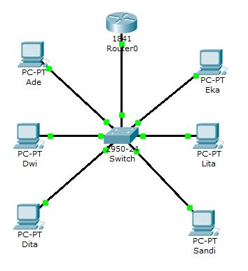
Buka aplikasi Packet Tracer
Lalu buat skema seperti gambar berikut

Atur IP Address untuk masing – masing komputer dengan cara mengklik PC yang dimaksud lalu pilih Desktop > IP Configuration

 Adapun alokasi IP yang saya gunakan adalah sebagai berikut:
Nama PC
IP Address
Subnet Mask
Ade
192.168.1.1
255.255.255.0
Dwi
192.168.1.2
255.255.255.0
Dita
192.168.1.3
255.255.255.0
Eka
192.168.1.4
255.255.255.0
Lita
192.168.1.5
255.255.255.0
Sandi
192.168.1.6
255.255.255.0


Ping ke setiap komputer untuk memastikan bahwa  komputer terkoneksi dengan baik. Saya melakukan ping dari PC Ade. Contoh hasilnya :

Packet Tracer PC Command Line 1.0
PC>ping 192.168.1.2

Pinging 192.168.1.2 with 32 bytes of data:

Reply from 192.168.1.2: bytes=32 time=120ms TTL=128
Reply from 192.168.1.2: bytes=32 time=40ms TTL=128

Ping statistics for 192.168.1.2:
    Packets: Sent = 4, Received = 4, Lost = 0 (0% loss),
Approximate round trip times in milli-seconds:
    Minimum = 40ms, Maximum = 120ms, Average = 60ms

PC>ping 192.168.1.3

Pinging 192.168.1.3 with 32 bytes of data:

Reply from 192.168.1.3: bytes=32 time=60ms TTL=128
Reply from 192.168.1.3: bytes=32 time=40ms TTL=128

Ping statistics for 192.168.1.3:
    Packets: Sent = 4, Received = 4, Lost = 0 (0% loss),
Approximate round trip times in milli-seconds:
    Minimum = 40ms, Maximum = 60ms, Average = 45ms

PC>ping 192.168.1.4

Pinging 192.168.1.4 with 32 bytes of data:

Reply from 192.168.1.4: bytes=32 time=70ms TTL=128
Reply from 192.168.1.4: bytes=32 time=40ms TTL=128

Ping statistics for 192.168.1.4:
    Packets: Sent = 4, Received = 4, Lost = 0 (0% loss),
Approximate round trip times in milli-seconds:
    Minimum = 40ms, Maximum = 70ms, Average = 47ms

PC>ping 192.168.1.5

Pinging 192.168.1.5 with 32 bytes of data:

Reply from 192.168.1.5: bytes=32 time=80ms TTL=128
Reply from 192.168.1.5: bytes=32 time=40ms TTL=128

Ping statistics for 192.168.1.5:
    Packets: Sent = 4, Received = 4, Lost = 0 (0% loss),
Approximate round trip times in milli-seconds:
    Minimum = 40ms, Maximum = 80ms, Average = 50ms

PC>ping 192.168.1.6

Pinging 192.168.1.6 with 32 bytes of data:

Reply from 192.168.1.6: bytes=32 time=70ms TTL=128
Reply from 192.168.1.6: bytes=32 time=40ms TTL=128

Ping statistics for 192.168.1.6:
    Packets: Sent = 4, Received = 4, Lost = 0 (0% loss),
Approximate round trip times in milli-seconds:
    Minimum = 40ms, Maximum = 70ms, Average = 47ms

Selanjutnya, kita buat VLAN dengan skema berikut:
Nama PC
Nama VLAN
Port
Ade
TKJ
Fa0/1, Fa0/2, Fa0/3
Dwi
Dita
Eka
TEI
Fa0/4, Fa0/5, Fa0/6
Lita
Sandi

Buat VLAN dengan cara mengklik Switch, pilih tab CLI dan ketikan perintah berikut ini :

Switch>en
Switch#configure terminal
Enter configuration commands, one per line.  End with CNTL/Z.
Switch(config)#vlan 2
Switch(config-vlan)#name TKJ
Switch(config-vlan)#ex
Switch(config)#vlan 3
Switch(config-vlan)#name TEI
Switch(config-vlan)#ex
Switch(config)#ex
Switch#
%SYS-5-CONFIG_I: Configured from console by console
Switch#show vlan brief

VLAN Name                             Status    Ports
---- -------------------------------- --------- -------------------------------
1    default                          active    Fa0/1, Fa0/2, Fa0/3, Fa0/4
                                                Fa0/5, Fa0/6, Fa0/7, Fa0/8
                                                Fa0/9, Fa0/10, Fa0/11, Fa0/12
                                                Fa0/13, Fa0/14, Fa0/15, Fa0/16
                                                Fa0/17, Fa0/18, Fa0/19, Fa0/20
                                                Fa0/21, Fa0/22, Fa0/23, Fa0/24
2    TKJ                              active   
3    TEI                              active   
1002 fddi-default                     active   
1003 token-ring-default               active   
1004 fddinet-default                  active   
1005 trnet-default                    active

Dari perintah tersebut, dapat dilihat bahwa VLAN dengan nama TKJ dan TEI telah dibuat, namun belum memiliki anggota. Untuk menambahkan anggotanya, klik Switch lalu pilih tab CLI dan ketikan perintah berikut.

Switch#conf term
Enter configuration commands, one per line.  End with CNTL/Z.
Switch(config)#int fa0/1
Switch(config-if)#switchport mode access
Switch(config-if)#switchport access vlan 2
Switch(config-if)#ex
Switch(config)#int fa0/1
Switch(config-if)#switchp mod ac
Switch(config-if)#switchp ac vlan 2
Switch(config-if)#ex
Switch(config)#int fa0/2
Switch(config-if)#switchp mod ac
Switch(config-if)#switchp ac vlan 2
Switch(config-if)#ex
Switch(config)#int fa0/3
Switch(config-if)#switchp mod ac
Switch(config-if)#switchp ac vlan 2
Switch(config-if)#ex
Switch(config)#int fa0/4
Switch(config-if)#switchp mod ac
Switch(config-if)#switchp ac vlan 3
Switch(config-if)#ex
Switch(config)#int fa0/5
Switch(config-if)#switchp mod ac
Switch(config-if)#switchp ac vlan 3
Switch(config-if)#ex
Switch(config)#int fa0/6
Switch(config-if)#switchp mod ac
Switch(config-if)#switchp ac vlan 3
Switch(config-if)#ex
Switch(config)#ex
Switch#
%SYS-5-CONFIG_I: Configured from console by console
Switch#show vlan b

VLAN Name                             Status    Ports
---- -------------------------------- --------- -------------------------------
1    default                          active    Fa0/7, Fa0/8, Fa0/9, Fa0/10
                                                Fa0/11, Fa0/12, Fa0/13, Fa0/14
                                                Fa0/15, Fa0/16, Fa0/17, Fa0/18
                                                Fa0/19, Fa0/20, Fa0/21, Fa0/22
                                                Fa0/23, Fa0/24
2    TKJ                              active    Fa0/1, Fa0/2, Fa0/3
3    TEI                              active    Fa0/4, Fa0/5, Fa0/6
1002 fddi-default                     active   
1003 token-ring-default               active   
1004 fddinet-default                  active   
1005 trnet-default                    active

VLAN telah selesai dibuat. Lalu tes koneksi antar PC dengan mengklik PC Ade dan ping ke semua komputer. Maka hasilnya akan seperti berikut.
Packet Tracer PC Command Line 1.0
PC>ping 192.168.1.2

Pinging 192.168.1.2 with 32 bytes of data:

Reply from 192.168.1.2: bytes=32 time=125ms TTL=128
Reply from 192.168.1.2: bytes=32 time=63ms TTL=128
Reply from 192.168.1.2: bytes=32 time=62ms TTL=128

Ping statistics for 192.168.1.2:
    Packets: Sent = 4, Received = 4, Lost = 0 (0% loss),
Approximate round trip times in milli-seconds:
    Minimum = 62ms, Maximum = 125ms, Average = 78ms

PC>ping 192.168.1.3

Pinging 192.168.1.3 with 32 bytes of data:

Reply from 192.168.1.3: bytes=32 time=111ms TTL=128
Reply from 192.168.1.3: bytes=32 time=47ms TTL=128
Reply from 192.168.1.3: bytes=32 time=30ms TTL=128
Reply from 192.168.1.3: bytes=32 time=47ms TTL=128

Ping statistics for 192.168.1.3:
    Packets: Sent = 4, Received = 4, Lost = 0 (0% loss),
Approximate round trip times in milli-seconds:
    Minimum = 30ms, Maximum = 111ms, Average = 58ms

PC>ping 192.168.1.4

Pinging 192.168.1.4 with 32 bytes of data:

Request timed out.
Request timed out.
Request timed out.
Request timed out.

Ping statistics for 192.168.1.4:
    Packets: Sent = 4, Received = 0, Lost = 4 (100% loss),

PC>ping 192.168.1.5

Pinging 192.168.1.5 with 32 bytes of data:

Request timed out.
Request timed out.
Request timed out.
Request timed out.

Ping statistics for 192.168.1.5:
    Packets: Sent = 4, Received = 0, Lost = 4 (100% loss),

PC>ping 192.168.1.6

Pinging 192.168.1.6 with 32 bytes of data:

Request timed out.
Request timed out.
Request timed out.
Request timed out.

Ping statistics for 192.168.1.6:
    Packets: Sent = 4, Received = 0, Lost = 4 (100% loss),

PC Ade tidak mampu terkoneksi dengan PC Eka, PC Lita dan PC Sandi karena berbeda VLAN.
Sampai disini konfigurasi VLAN part I telah selesai, namun VLAN belum dapat berfungsi dengan baik karena seluruh PC belum dapat saling terkoneksi.
Semoga bermanfaat dan selamat mencoba.
Part II